| |
 |
| |
 |
| 1 What is the Radiation Shape Factor? |
| 2 Definitions of the Radiation Shape Factor (View Factor) |
| 3 Radiation Shape Factor (View Factor) of Typical Shapes |
| 3-(1) Disk 1 and Sphere 2 |
| 3-(2) Parallel Rectangles of the Same Shape 1 and 2 |
| 3-(3) Parallel Disks with Radii R1 and R2 |
| 3-(4) Rectangles Perpendicular 1 and 2 to Each Other |
| 4 Application of Radiation Shape Factor (View Factor) to Actual Furnaces |
| 4-(1) Example of Radiation Shape Factor (View Factor) for Rotary Heath Furnaces |
| |
| |
 |
| 1 What is the Radiation Shape Factor? |
| |
| Radiation Shape Factor (View Factor) is the very important number for the calculation of thermal (heat) radiation. |
| |
| Thermal radiation occurs when an object emits electromagnetic waves proportional to the fourth power of tits absolute temperature. (See "Basis" and "Radiation" for detail.) The proportionality coefficient when calculating the thermal radiation of a black body is the Boltzmann coefficient. When calculating the thermal radiation of a real object, multiple coefficients such as area, emissivity, and positional relationships are necessary. |
| |
| The positional relationship between the heat sources and the object is the radiation shape factor. The radiation shape factor (view factor) is calculated based on the shape and layout of the heat (radiation) sauces and to-be-heated object. Therefore, appropriate drawings are necessary. For example, they are the structural drawings of the heating furnace and the heat treatment furnace, which you are going to analyze, the shapes of the to-be-heated materials, locations of the materials in the furnaces. |
| |
| How does a thermal radiation work? Firstly, the reality of thermal radiation is done by electromagnetic waves. Electromagnetic waves travel straight from the heat source and are reflected when they hit obstacles such as hanging objects or uneven surfaces inside the furnace. Therefore, from the viewpoint of the to-be-heated material, there will be a couple of "shadow" areas where the electromagnetic waves from the heat source will not reach the material or will be attenuated. |
| |
| The following pictures show the heat sources in red, and the to-be-heated material in black. In the picture on the left, a certain point on the material receives heat radiation from the entire heat source because there is no obstruction. In the right, there is a shield (shown in gray) between the heat source and the material, therefore, heat radiation from the shielded area of the heat source does note reach the material. |
| |
 |
| |
| In large heating furnaces and heat treatment furnaces, multiple materials can be heated at the same time. The materials move continuously in the furnace, the relative arrangement between the furnace internal structures and the material changes from time to time. In other words, from the viewpoint of the material that receive radiant heat, due to the continuous change of its position, the view factor (radiation shape factor) changes time to time. |
| |
| There are a couple of ways how to deal with the thermal radiation, including the ray tracing method, the view factor from time to time, and representative view factor of a range of positions in the furnace. It is suggested to come to an agreement with all the parties involved which way to take. |
| |
| For example, the explicit method of the numerical analysis sequentially follow the changes over time to time, therefore, the radiation shape factor (view factor) can be calculated each time. It may be possible to simplify the calculation method depending on the purpose of the analysis. |
| |
 |
| 2 Definitions of the Radiation Shape Factor (View Factor) |
| |
| The Radiation Shape Factor (View Factor) is calculated by utilizing solid angles over the field of view. Please let me skip the detail but the summary. |
| |
| The Radiation Shape Factor (View Factor) is defined as the ratio of the energy leaving the heat source (Source) and entering the to-be-heated material (Target) to the total radiant energy of the Source. |
| |
 |
| |
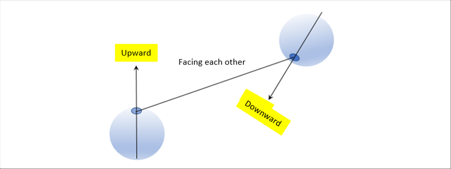
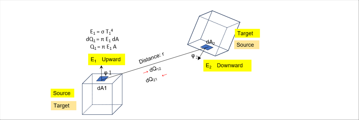
| The following picture shows the general positional relationship between the heat source (Source) and the material (Target). At a minimum, they shall be facing each other. |
| |
 |
| |
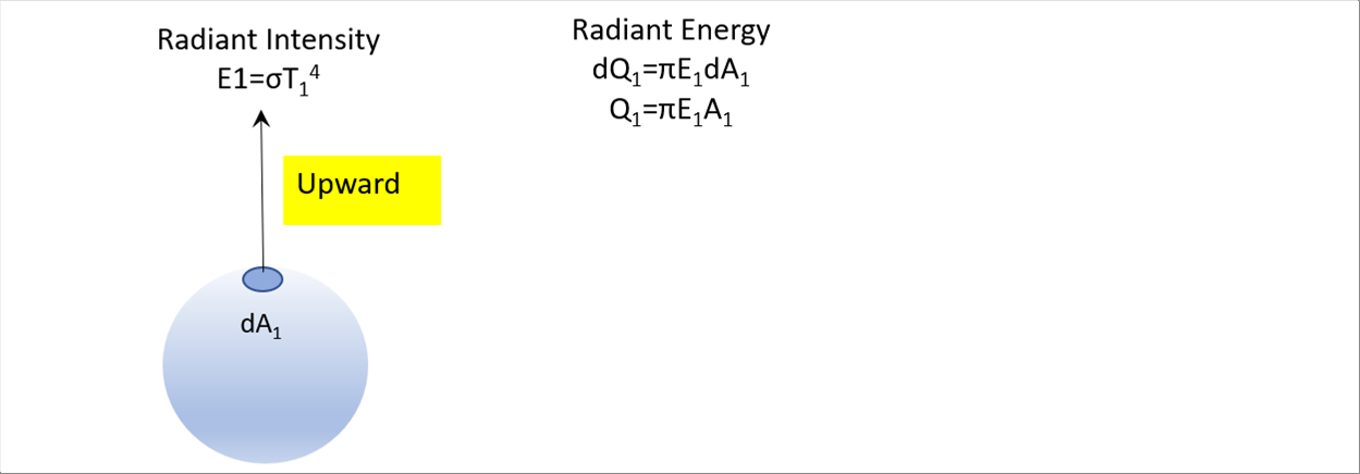
| Set the left bottom eyeball as 1, and the right top one as 2. Assume the iris part as the minute area dA. Hence, the radiant intensity E and the radiant energy Q are as follows. |
| |
 |
| |
 |
| |
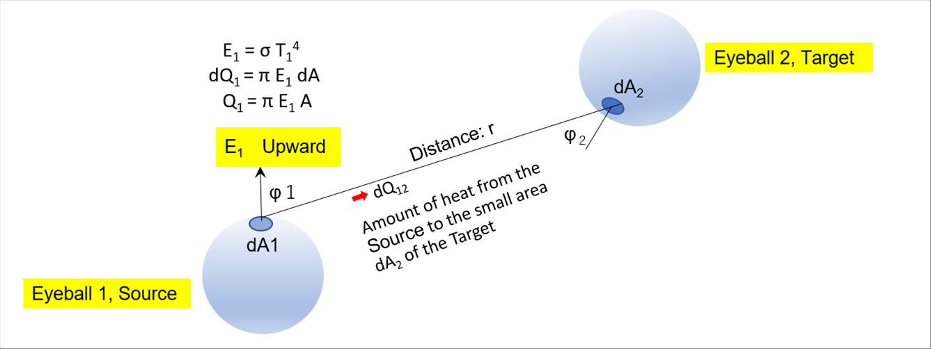
| The following picture shows two angles from the plumb line of the Source and of the Target, two small areas that face each other, the radiant intensity from the small area dA1, the distance between the two areas, and the amount of heat from the Source. |
| |
 |
| |
| The amount of heat dQ12 that leaves the eyeball 1 and enters the small are dA2 of the eyeball 2 in the upper right corner is defined as follows using the solid angle omega. |
| |
 |
| |
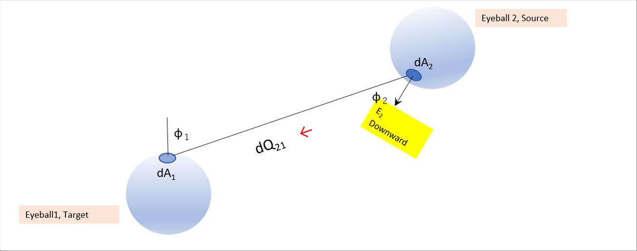
| Aat the same time, heat radiation in the opposite direction is also occurring. |
| |
 |
| |
| dQ21 is as follows. |
| |
 |
| |
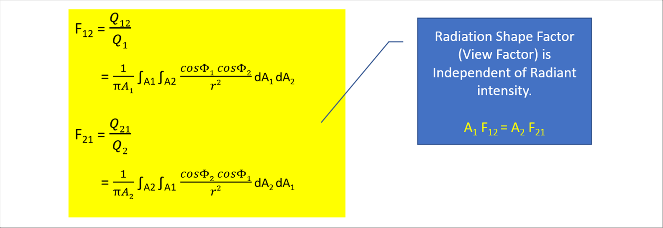
| Substitute the dQ12 and dQ21 into the definition of the Radiation Shape Factor (View Factor), F12 = Q12 / Q1 AF21 = Q21 / Q1. |
| |
 |
| |
| Radiation Shape Factor (View Factor) is independent of radiant intensity. The Radiation Shape Factor (View Factor) depends only on area and relative angles. Once one (1) is known, the other is easily obtained using areas ratio. |
| |
| We reviewed eyeballs to make the positional relationship easier to understand; however, the same expressions hold true for cuboids, cubes, or flat plates. |
| |
 |
| |
 |
| 3 Radiation Shape Factor (View Factor) of Typical Shapes |
| |
 |
| 3-(1) Disk 1 and Sphere 2 |
| |
 |
| |
 |
| 3-(2) Parallel Rectangles of the Same Shape 1 and 2 |
| |
 |
| |
 |
| 3-(3) Parallel Disks with Radii R1 and R2 |
| |
 |
| |
 |
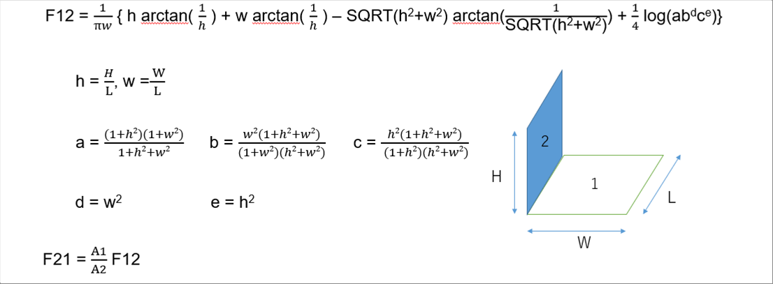
| 3-(4) Rectangles Perpendicular 1 and 2 to Each Other |
| |
 |
| |
 |
| 4 Application of Radiation Shape Factor (View Factor) to Actual Furnaces |
| |
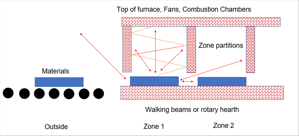
| Actual heating furnaces are equipped with walking beams, rotating hearth, zone partition walls, etc inside the furnaces., and therefore, their interiors show more complex shapes than those of examples above. It is suggested to carefully consider how to handle the radiation shape factor (view factor) of the inside of the furnaces based on the drawings, and then agree on the view factor. |
| |
 |
| |
| Once you decide on a calculation way, you can calculate it online each time, or you can create a database for each position of the furnace in advance. |
| |
| When the materials are round steel bars, the following same condition will happen. |
| |
 |
| |
| The partitions and the top of the furnace next to the current zone can be skipped, because they are far and scarcely visible from the material. The materials both sides of the material may be skipped, because the temperature difference between adjacent materials is small. little difference of temperatures between the materials is small. It may be assumed that the factors for blind spots and parts with complect shapes cancel each other out. There may be no problem in adopting other assumptions that are considered reasonable or optimal for the locations you need to analyze. |
| |
 |
| 4-(1) Example of Radiation Shape Factor (View Factor) for Rotary Heath Furnaces |
| |
 |
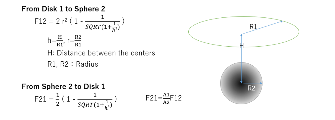
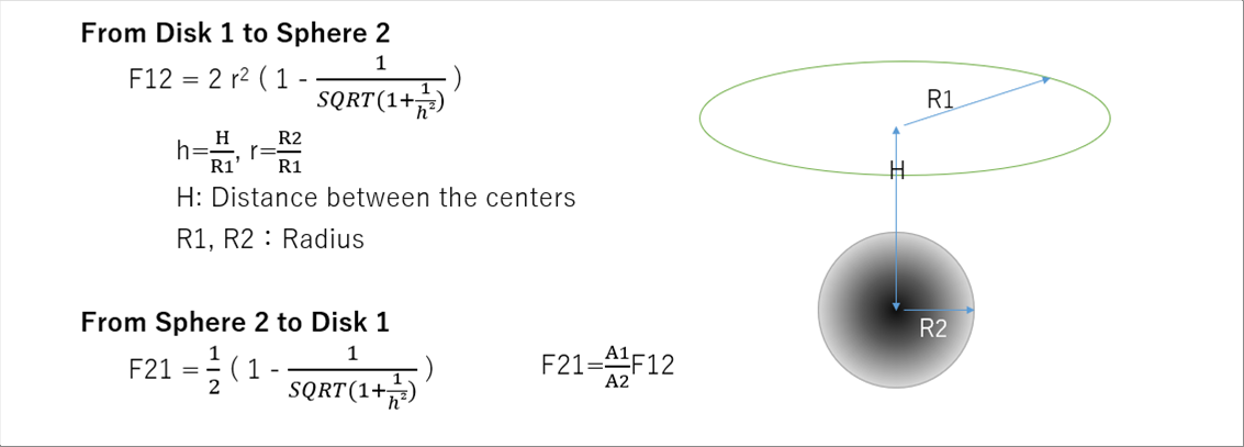
| It should be difficult to get the correct radiation shape factor (view factor), because the the shape of round bar is cylindrical. Let's adopt the 3-(1) disk and sphere instead. |
| |
 |
| |
| Width of zone 3000mm, Ceiling 1000mm, Diameter 170mm, F12 = 0.003078 |
| F21=0.2396 |
| |
| |
| |
| Author: T. Oda |
| The page was prepared in Excel, and html and css files were automatically generated by the excel2web. |


