| |
 |
| |
 |
| 1 Pressure Loss Calculation Methods and Exercise |
| 1-(1) Exercise, Bernoulli's Theorem |
| 1-(2) Pressure Loss |
| Step 1: Calculation of Reynolds Number |
| Step 2: Calculation of Pipe Friction Coefficient, Moody Diagram or Formulas |
| Step 3: Pressure Loss Calculation |
| Step 3-1a Pipe Coefficient of Friction, Moody Diagram |
| Step 3-1b Pipe Friction Coefficient: Fanning's Formula |
| Note Two Friction Coefficients, Darcy's Formula |
| Step 3-2a Pressure Loss Coefficient, Straight Pipe Part |
| Step 3-2b Pressure Loss of Elbows, T, Gate Valves |
| Step 4 Example of Pressure Loss Calculation |
| 2 Pressure Loss Factors for Various Fitting Types |
| 2-1 Pipe Inlets from Tanks |
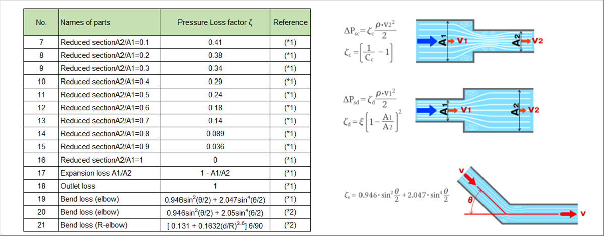
| 2-2 Pipe Cross-Sectional Area and Angle Change |
| 2-3 Fully Open Globe Valves |
| 2-4 Gate Valves by Opening Ratio |
| 2-5 Branching Piping |
| |
 |
| 1 Pressure Loss Calculation Methods and Exercise |
| |
 |
| 1-(1) Exercise, Bernoulli's Theorem |
| |
| As shown in the picture below, let's consider the case where the pump is on the first floor and the nozzle is on the second floor. |
| |
 |
| |
| The discharge pressure can be calculate using Bernoulli's theorem with pressure loss, point one (1) is the pump position and point two (2) is the nozzle position. |
| |
| The specification of pump, density of water, and the pressure loss are given, so we can calculate the discharge pressure by simple calculation, which is 0.78 Mpa. |
| |
| What to note in the calculation is that the units shall be aligned. The pump discharge rate is one hundred (100) liters per minute, the pump outlet pressure is megapascals, the pressure loss is kilopascals, the piping and nozzles are millimeters, and the density is cubic meters. |
| |
 |
| 1-(2) Pressure Loss |
| |
| Now, we know that if the pressure loss is known, other numerical values can be obtained by simple calculation. However, it is very rare to know it except in the exercise described above. (The author thinks.) If it already exists, it is most accurate to measure it, but as with the material mechanics, we want to know the pressure loss in advance. |
| |
| In the material mechanics, it is possible to calculate what we want to know in advance, such as Young(s modulus and cross-sectional quadratic moment. However in fluid dynamics, there is a troublesome problem that the state of flow changes with the Reynolds number. (This is the author's personal opinion.) |
| |
| The protocol for calculating the pressure loss is to first calculate the Reynolds number, and since the flow pass is often pipes, the pipe friction coefficient is calculated. Finally, calculate the pressure loss. The author thinks that specialized companies use more modern and advanced methods, but if you want to calculate is yourself, you can calculate it in the way. |
| |
 |
| Step 1: Calculation of Reynolds Number |
| |
| Please find the following costeps. |
| 1-1 Fluid velocity calculation |
| 1-2 Density calculation |
| 1-2-1 Gases are expressed in numerical vlaues of standard states, 101.3 kPa, zero dengrees C., 0.0224 m3/mol |
| 1-2-2 Temperature conpensation of gasses, ƒÏ=m*(101.3+P)*273/(0.0224*1000*101.3*(273+T)) |
| 1-2-3 Molar mass m [g/mol], P [kPaG],T [deg. C] |
| 1-3 Viscosity Examination |
| 1-4 Reynolds number Re Calculation |
| |
 |
| Step 2: Calculation of Pipe Friction Coefficient, Moody Diagram or Formulas |
| |
| Calculation of Pipe Friction Coefficient can be obtained by a Moody diagram or formulas. How to read the Moody diagram is explained in Step 3-1a. |
| |
| |
 |
| |
 |
| Step 3: Pressure Loss Calculation |
| |
| Pressure Loss = A + B |
| A: Calculate the equivalent length of the elbows, etc., and use Fanning's formula to calculate the total pipe length. |
| B: Calculate the pressure loss at the inlet from a tank, cross sectional changes in reductin and expansion, and pipe outlet . |
| |
 |
| Step 3-1a Pipe Coefficient of Friction, Moody Diagram |
| |
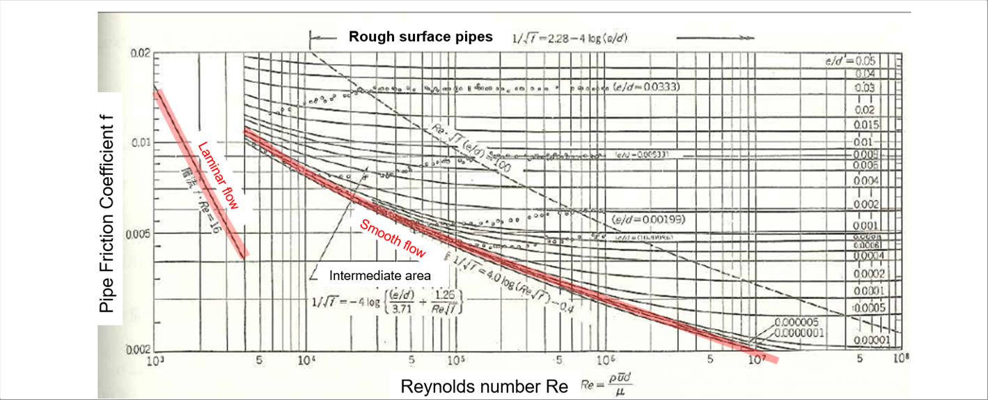
| Moody diagram |
| |
| The Moody diagram reads the pipe friction coefficient from the Reynolds number and relative roughness e/d. It is versatile because if covers a fairly wide range, but to be honest, it is hard to read. In our normal work, we want to know the friction coefficient in a narrower range than that of the Moody diagram's, so the author suggests to create an experimental formula that suites the conditions. |
| |
| The roughness of the inside surface of the tubes and pipes has a significant impact on the Reynolds number. Since the Moody diagram uses relative values, it can be said that it is dimensionless and covers a wide range of materials. Again, I think it is too broad for the daily works. (My personal opinion.) |
| |
| The best way to get the relative roughness is to measure it of the material you plan to use, but I do not think it will have a big impact if we use the table below as a guide. |
| |
 |
 |
| |
 |
| Step 3-1b Pipe Friction Coefficient: Fanning's Formula |
| |
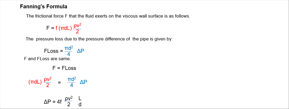
| The friction coefficient for Fanning's formula can be deribed as: |
| |
 |
| |
| (1) Laminar flow (Re<= 3 000) regardless of the roughness of inside surface: f = 16/Re |
| (2) Transition flow: The author omits it. |
| (2) Turbulent flow, Smooth surface pipes and tubings (3 000 < Re < 10^5): Blasius' formula f = 0.0791 * Re^(-0.25) (Probably the most famouos) |
| (3) Turnulent flow, Rough surface pipes and tubings (3000 < Re < 10^7): f = 1 / { 2.28 - 4 log10(e/d) } ^2 |
| |
| When we consider the friction coefficient, the inside surface is a concern; however, but the coefficient of friction for laminar flow is determined only by the Reynolds number, and that of the turbulent flow is calculated by two (2) formulas. So, we may not need to worry too much. |
| |
 |
| |
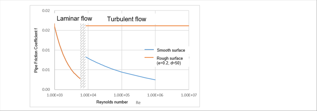
| If we make a graph like the Moody diagram, it will like the above. Since the equation is not continuous for laminar flow and turbulent flow, that part is a wave pattern. When you do simulation or calculation, once the Reynolds number becomes a transition region, the author thinks it is safe to consider either laminar or turbulent numbers. The best way may be to keep the Reynolds number away from the transition range. |
| |
 |
| Note Two Friction Coefficients, Darcy's Formula |
| |
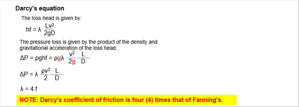
| The pressure loss head hf in Bernoulli's theorem is given as follows. Lambda is called Darcy's coefficient of friction. |
| |
 |
| |
| Darcy's coefficient of friction Lambda is four (4) times that of f in Fanning's formula. TS Consulting's website uses different symbols in order to avoid confusion, but both are referred to as "friction coefficient". When reading friction coefficient in a Moody diagram, you should also be careful which of the two coefficients of friction is the y-axis. When calculating the pressure loss, f shall be multiplied by four (4) while Lambda is used as is. |
| |
 |
| Step 3-2a Pressure Loss Coefficient, Straight Pipe Part |
| |
| Once the friction coefficient is determined, the pressure loss can be calculated by velocity, pipe length, inside diameter, etc. If the flow path is bent or there is valves, further pressure losses will occur. However, since the pressure losses of those parts are calculated by correcting the length of the straight pipes, it is important to calculate the pressure loss of the straight one. |
| |
| Pressure loss of the straight pipe |
| |
 |
| |
| |
 |
| Step 3-2b Pressure Loss of Elbows, T, Gate Valves |
| |
| Depending on the shape, use the converted equivalent length instead of the pipe length L. |
| |
 |
| 45 degrees elbow: n=15, 90 degrees elbow: n=15 - 32. |
| T-tubes: n= 40 - 90 |
| Gate valves: Full open n=1 - 7, 3/4 open : n=40, 1/2 open : n= 200, 1/4 open: n=800. |
| |
 |
| Step 4 Example of Pressure Loss Calculation |
| |
 |
| |
| Calculation |
| (1) Re=54.1*10^(-3)*1.2*1000/( 0.797*10^(-3) ) = 81455 Turbulent flow |
| (2) f = 0.0791*Re^(-0.25)=4.682*10^(-3) |
| (3) Pressure Loss |
| (3)-1 Conversion length, 90 degrees elbow: 15*54.1mm*6 = 4.9 m |
| (3)-2 Conversion length, T-tube: 80*54.1mmX2 = 8.7 m |
| (3)-3 Total length L = 100+4.9+8.7 = 113.6 |
| (4) Pressure loss =4f x 0.5ƒÏv^2 *L/D = 28.32 [kPa] |
| |
 |
| 2 Pressure Loss Factors for Various Fitting Types |
| |
| There are a lot of pressure loss factors are available, and the author picked up some of them. The homepages used are as follows. |
| |
| When you click on some links, you may be re-directed to a scam one, so the author will prefer the graphical presentation. (The internal links in TS Consulting's menu supports tabnabbing as a measure against phishing scams.) |
| |
 |
| |
 |
| 2-1 Pipe Inlets from Tanks |
| |
 |
| |
 |
| 2-2 Pipe Cross-Sectional Area and Angle Change |
| |
 |
| |
 |
| 2-3 Fully Open Globe Valves |
| |
 |
| |
 |
| 2-4 Gate Valves by Opening Ratio |
| |
 |
| |
 |
| 2-5 Branching Piping |
| |
 |
| |
| |
| Author: T. Oda |
| The page was prepared in Excel, and html and css files were automatically generated by the excel2web. |


